Now that I have decided on using a C6 Corvette ZR1 reae hub on all 4 corners, I can look for brake kits that fit on that 5×4.75″ pattern hub.
Design considerations for the brakes are
Size (biggest brake that will fit inside 18″ wheels)
Availability & Price (readily available in the second hand market for under $2000)
Fits on 5×4.75″ pattern hubs
6 Piston front & 4 Piston rear Brembo calipers
Options I have considered are:
C6 Corvette Z06 14″x32mm 6 Piston Fronts
C7 Corvette Z06 14.6″ 6 Piston Fronts (too big for 18’s)
C7 Corvette ZR1 Carbon Brakes 15″ 6 Piston Fronts (too big for 18s)
I found a set of 14″ C6 Z06 brakes that will fit under 18″ wheels for $1500 on ebay and locked those in.
Disclaimer: I don’t know what i’m doing. But this site is a chronicle of my figuring it out. There is probably a better way to do what I have outlined here, and I will eventually make my way there eventually.
These posts will serve as a historical archive of long format information dumps of where my mind was at the time of writing, for refreshing my memory in the future and tracking my own progress.
I often learn by doing something wrong until I figure out how to do it less wrong. Readers should not take these posts as instructional. These are a record of what I did, not what should be done, and they are not meant to be used as how-to’s.
In short, You should not do what I do unless you love the pain of failure.
I now have an initial starting point for a Tire, an overall vehicle width and length, an engine, transmission, and differentials. The next step in my process is to build out the part of the suspension that is inside the wheel. Wheel Hub, Spindle, and Brakes.
I first considered using an existing spindle to avoid having to make one myself, but I think once I get to the step of designing the control arm mounting points, I am going to want more geometric flexibility than a pre-made spindle will give me.
For this reason, I am going to attempt to make my own modular spindle with removable mounting points for the upper and lower control arm mounts, steering arm, and brake mounting brackets.
I will start with picking an OEM hub. This is something I don’t want to design from scratch. My selection criteria for a wheel hub are
Overall strength
Mounting convenience
Spline count and diameter
Speed sensor
Lug Pattern
affordable OEM Big Brake availability
I want a hub that bolts to the spindle with a flange, so the wheel stays attached to the car if the axle breaks.
I want a strong hub that has provisions for a beefy spline through the center, a convenient mounting flange, a common lug pattern that comes from a car with an affordable oem 6 piston big brake option, and has an integrated speed sensor. And the plan is to run this same hub on all 4 corners.
After looking through some options, I found that the 2009-2013 Chevrolet Corvette ZR1 rear wheel bearing had provisions for a large diameter 33 spline shaft, a convenient 4 bolt mounting flange, an integrated speed sensor with a pig tail connector, and a 5×4.75″ lug pattern that can accept the relatively affordable OEM Chevrolet C7 Corvette Z06 14.6″ 6 Piston Brembo Brake Kit
Disclaimer: I don’t know what i’m doing. But this site is a chronicle of my figuring it out. There is probably a better way to do what I have outlined here, and I will eventually make my way there eventually.
These posts will serve as a historical archive of long format information dumps of where my mind was at the time of writing, for refreshing my memory in the future and tracking my own progress.
I often learn by doing something wrong until I figure out how to do it less wrong. Readers should not take these posts as instructional. These are a record of what I did, not what should be done, and they are not meant to be used as how-to’s.
In short, You should not do what I do unless you love the pain of failure.
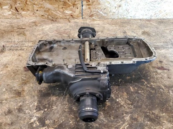
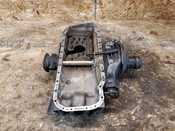
The front and rear differentials will be mounted to the chassis like a 2020 Ford F150, not through the oil sump like a Nissan GTR or AWD BMW.
The front and rear differentials don’t need to be from the same vehicle, but they do need to have matching final drives.
Ideally the differentials would be readily available at an affordable price, and have a wide range of final drive ring gear options so i can fine tune the gearing mph/rpm of the shift points. Also, they should either be strong enough from the factory to support the power goal, or have enough aftermarket support to allow for them to be built up to support the power goal.
I am considering 3 options
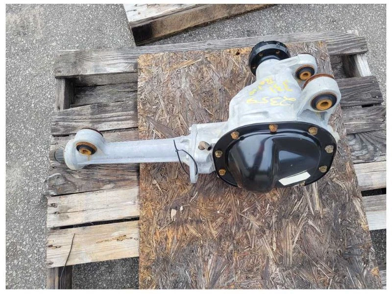
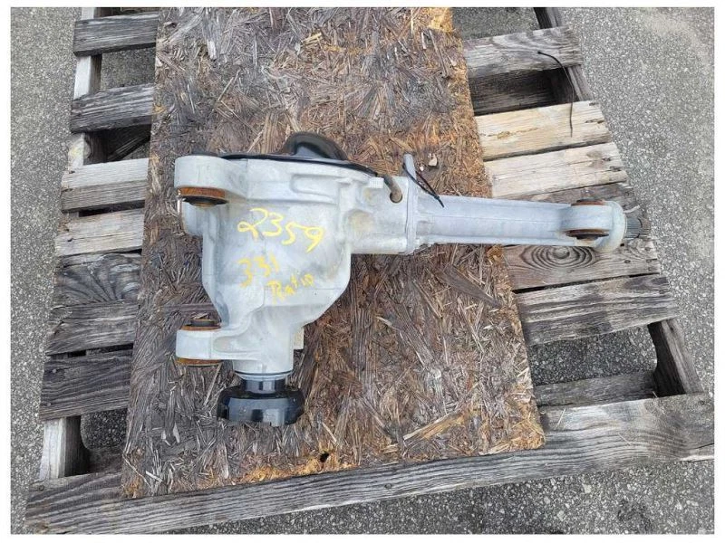
Ford 8.8″ IFS & IRS Diffs The 2020 Ford F150 came with an affordable 8.8″ aluminum housing chassis mounted independent front differential that comes with a housing that has a built in intermediate shaft housing so that both front axles can be equal length and has lots of ring gear options for different final drives. It lives relatively well in 1000whp twin turbo Coyote v8 F150 4WD drag racing applications. The 2010 Ford Explorer came with an affordable 8.8″ aluminum housing independent rear differential with lots of ring gear options for different final drives. It is a very popular rear end upgrade for many vehicles. The downside here is that the 8.8″ front diff is physically very large to fit in front of the engine. Since it has a built in intermediate shaft, and ideally the front axles would be the same length, I would want to use it with an engine that is narrow enough to allow for the front diff to be centered (left to right) in the frame without hitting the engine. Final drive ratios of 3.09, 3.15, 3.27, 3.31, 3.55, 3.73, 4.10, and 4.56 are available.
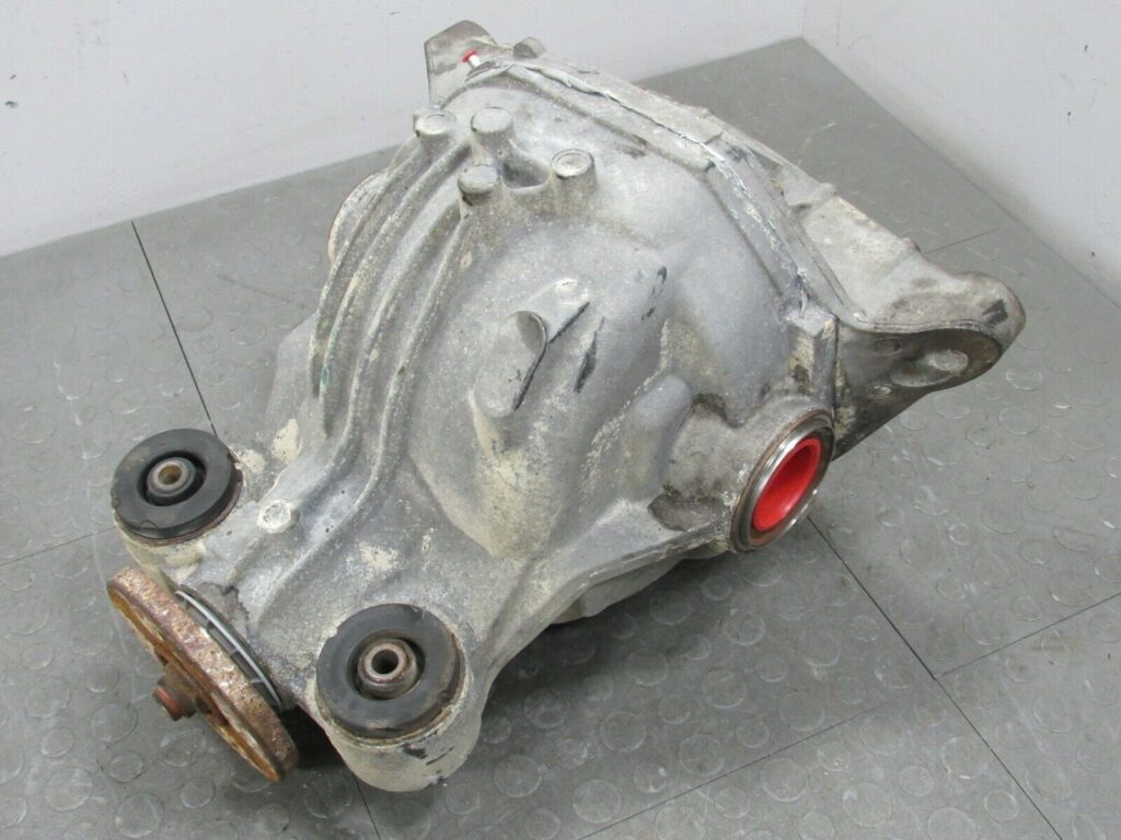
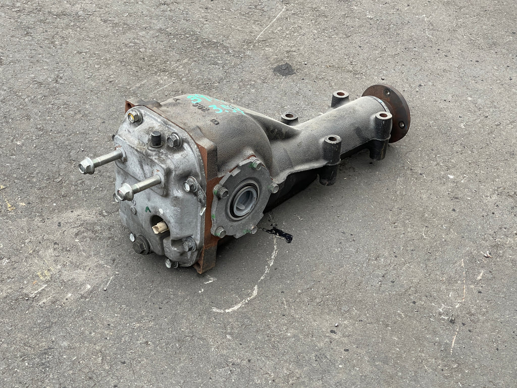
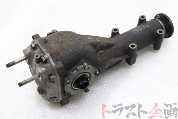
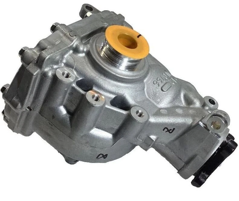
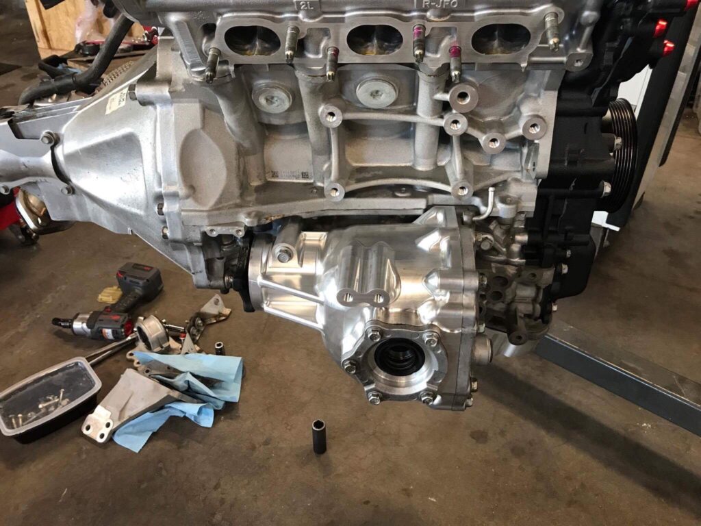
Two Subaru Rear Diffs (one turned around and flipped upside down in front) Subaru makes a strong but compact R180 rear differential, and an even smaller R160 rear differential with matching ring gear ratios and both came as LSD’s from the factory. The smaller R160 rear differential could be turned around and flipped upside down to be used as a front differential. These diffs are readily available, strong, compact, and reasonably affordable. But the front one will require an intermediate shaft and carrier to be fabricated so that the front axles can be the same length. Final drive ratios of 3.54, 3.90, and 4.44 are available.
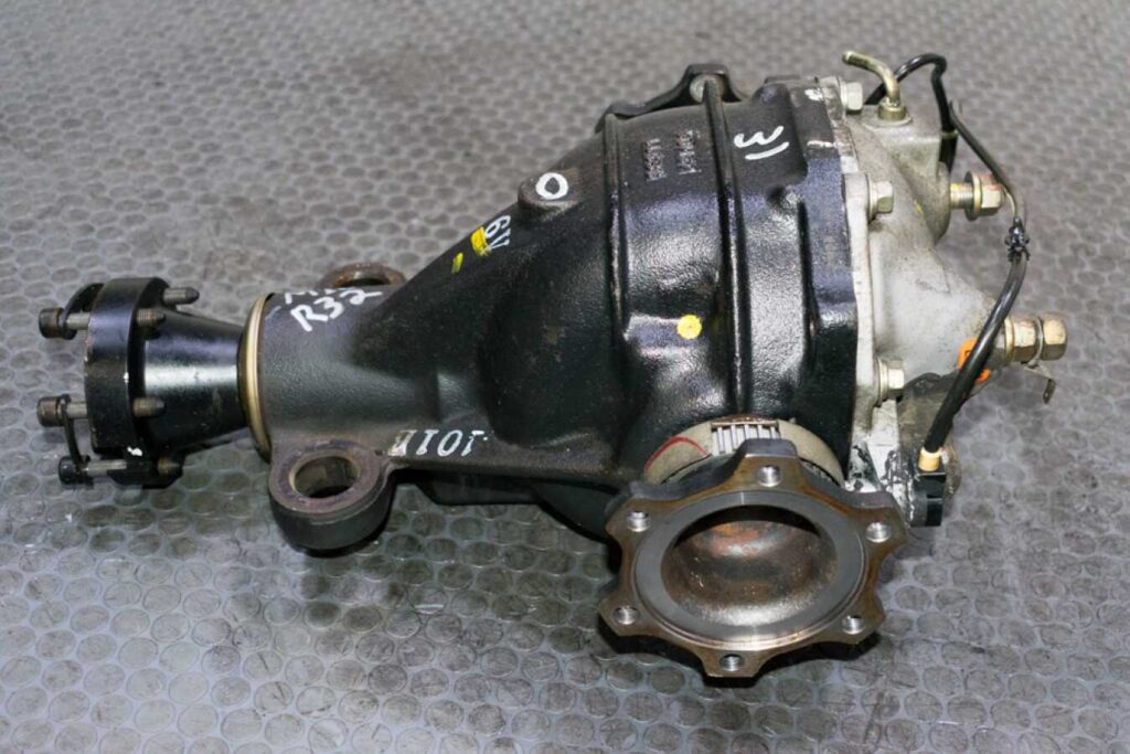
Nissan GTR Front and Rear Diffs The Nissan GT-R front diff is designed to mount to the oil pan and the engine sits on top of the axle line. But a bracket could be fabricated to chassis mount it in front of the engine. These diffs are strong and small, but they are expensive and less readily available. The R32 differentials have a final drive of 4.11 and the R35 final drive is 3.70
some considerations:
The Toyota 2JZ engine has the turbos on the right side of the car. The turbos are one of the heavier components in the car that can be strategically placed for center of gravity optimization. Ideally they would be mounted as low and centered as possibly without negatively impacting their ability to gravity drain oil into the sump. Then there must be room for the down pipes and exhaust to come out of the turbos and down the tunnel to the back of the car. And in addition to all of that, there is also an engine mount in that same area. This would make a right side driveshaft configuration (like the Nissan gtr) more difficult to package. The turbos would have to be top mounted with the driveshaft running under them and the exhaust would have to pass around the front driveshaft somehow.
Disclaimer: I don’t know what i’m doing. But this site is a chronicle of my figuring it out. There is probably a better way to do what I have outlined here, and I will eventually make my way there eventually.
These posts will serve as a historical archive of long format information dumps of where my mind was at the time of writing, for refreshing my memory in the future and tracking my own progress.
I often learn by doing something wrong until I figure out how to do it less wrong. Readers should not take these posts as instructional. These are a record of what I did, not what should be done, and they are not meant to be used as how-to’s.
In short, You should not do what I do unless you love the pain of failure.
The layout will be front-mid-engine (FM), all wheel drive (AWD). The engine and transmission will both be completely between the front and rear axle lines.
I will use a chassis mounted front differential that passes the front axles in front of the engine like a 2020 Ford F150 instead of through the oil pan like a Nissan GTR or a BMW. So the engine and transmission will be moved backwards until the engine is completely behind the front axle line. This will allow me to lower the engine and transmission as low as it can be mounted to lower the center of gravity.
Engine
There are lots of engines that can make 900-1000whp on fuel that can be found at public gas stations but I have to narrow it down to just 1. So I will make a list of engines that I like, and then narrow it down with selection criteria.
Ideally I would pick an engine and transmission combo that an adapter solution already exists for from Domiworks or Adamat
Selection criteria:
Price
Engine Availability
Adapter Availability
Powerband & Responsiveness
Aftermarket Support
Physical Size
Weight
Longevity
Sound
Ease of maintenance
Some engines that I like that will make 1000whp on E85, and have both ZF 8HP and Quaife Sequential adapter solutions available are
Ford Coyote V8 (Turbocharged or Supercharged)
Chevrolet LS V8 (Turbocharged or Supercharged)
Toyota 2JZ-GTE I6 (Turbocharged)
Nissan RB26DETT I6 (Turbocharged)
Honda K-Series I4 (Turbocharged)
I would like for the powerband of the 1000whp to be wide and responsive. I want to be able to accelerate quickly out of a turn that I failed to carry enough momentum through. A laggy power delivery that comes on late and all at once will not be forgiving in that scenario. Engines with larger displacement will be more responsive and spreading the 1000whp of power over more cylinders should help the engine live the longest. So for those reasons, I want the biggest engine on the list. But more displacement and more cylinders almost certainly means more size and weight.
Since the car will be mid-engine all wheel drive with the engine in front of the driver and behind the front differential, the engine will have to be short enough in length to fit within the proposed wheelbase with the transmission, and narrow enough for a driveshaft to route around one side or the other to a chassis mounted front differential. I also don’t want to add more weight to the car than I have to. So for those reasons, I want the smallest engine that will meet the horsepower goal.
The smallest and lightest engine on my list that can make 1000whp on E85 is the 4 cylinder Honda K-Series. Looking through the criteria, it is affordable and readily available. As of 2026, long blocks can be found quickly and easily for around $1000. It’s physically small, lightweight, and easy to work on. But it is the worst sounding engine on the list, and because it only has 4 cylinders, that means each cylinder has to support 250whp so it is likely to have the worst longevity of the engines on the list at 1000whp.
The Ford Coyote and Chevy LS 8 cylinder engines will both live the longest at 1000whp (125whp/cyl) and are readily available. They can meet the power goal with a supercharger or small turbos. They will provide the broadest and most responsive 1000whp powerbands on the list. But they are physically large so they might make awd packaging more complicated and they are heavy.
The inline 6 cylinder engines on the list are the “happy medium” between the smallest and biggest engines on the list. They can make a 1000whp (167whp) powerband that is more responsive than the one provided by the K-Series, and are physically narrower than the LS and Coyote engines. Of the 2 inline 6 cylinder options on the list, the Nissan RB26 engine is relatively expensive and harder to get compared to the Toyota 2JZ.
I have personal experience with 4 digit horsepower 2JZ engines and I like the sound. It is not the cheapest engine on the list, but the newer versions with variable cam timing can be had for under $5000. The aftermarket support is extensive for this engine so I wont have any problem finding parts even if I want to significantly increase the displacement or change the rod/stroke ratio. The left side of the engine has plenty of room for a driveshaft since there wont be power steering or air conditioning accessories in the way. I am going to choose the 2JZ to move forward with.
2JZ Pros
2JZ-GE VVTi OEM Core Engine Priced under $1000
Narrow width accommodates a chassis mounted front diff nicely
Variable Valve Timing for maximizing area under the power curve
Strong aftermarket support
Upgraded block casting available through Dart
Multiple off-the-shelf stroker crankshaft options allowing displacement of 3.0L-3.5L
Multiple off-the-shelf rod length options to adjust rod stroke ratio if needed later
Off-the-shelf dry sump options available
Sounds cool
Revs to 8500-9000rpm safely
Lives well at 1000whp when built
2JZ Cons
Only has 6 cylinders
Relatively heavy for a 6cyl
Will require using ethanol fuel to live at 1000whp
The plan at the time of writing this, is to start with a 3.0L OEM 2JZ VVTi engine with two relatively small reverse-rotation turbos and a custom turbo kit that routes both down pipes to their own separate exhaust pipes that lead to the back of the car. Then once the car is running, I will swap in a built stroker 2JZ with increased displacement to improve the power band and responsiveness even more.
Transmission
Transmission options that will be considered are:
Nissan R32 Skyline GT-R AWD Quaife 6spd Sequential Transmission and Transfer case
BMW ZF 8HP AWD 8spd Automatic Transmission and Transfer case
The Nissan transmission and transfer case route the front driveshaft up the right side of the engine, while the BMW transmission and transfer case routes the front driveshaft up the left side of the engine. This will need to be a consideration moving forward once I get to the task of choosing differentials and packaging the other required parts of the car.
The front to rear power split is adjustable in the Nissan transfer case and can be controlled by the ECU.
The BMW transfer case routes power to the front and back using an electronically controlled clutch system that will require an aftermarket electronic controller to operate. If a controller is not available, Domiworks makes adapters to adapt other transfer cases to the ZF 8HP transmission (including the Nissan GTR transfer case).
Both transmissions can be shifted with paddles.
Momentum Motorsports offers a 2JZ bolt on kit for the Quaife GTR sequential transmission, and Domiworks makes a 2jz adapter for the BMW ZF 8HP transmission.
The Quaife GTR Sequential is expensive up front, while the 8HP is inexpensive up front but ends up being expensive when its time to make 1000whp reliably.
Disclaimer: I don’t know what i’m doing. But this site is a chronicle of my figuring it out. There is probably a better way to do what I have outlined here, and I will eventually make my way there eventually.
These posts will serve as a historical archive of long format information dumps of where my mind was at the time of writing, for refreshing my memory in the future and tracking my own progress.
I often learn by doing something wrong until I figure out how to do it less wrong. Readers should not take these posts as instructional. These are a record of what I did, not what should be done, and they are not meant to be used as how-to’s.
In short, You should not do what I do unless you love the pain of failure.
I’ll need to pick a wheel base and track width to draw my first lines in Fusion. But these two dimensions work together to create a personality of how the car will behave. The track width is the distance between the center lines of the tires when viewing from the front or rear of the car. The wheelbase is the length between the center of the circle drawn by the front and rear tire when viewing from the side of the car. The track ratio is the ratio created by dividing the track width by the wheel base. Text book theory says that a higher track ratio (wider width and shorter wheel base) as better cornering potential than a lower track ratio, and that a lower track ratio goes in a straight line better (like a long narrow dragster). This leaves us with an equation that has 3 variables.
For the sake of making this next step easy, I will oversimplify the concept of how TrackRatio affects drivability as a sliding scale between
A.) Maximum cornering ability, and minimum stability in straights
on one side, and
B.) Maximum stability in straights, and minimum cornering ability
on the other.
I want a reasonable mix of both, so I will be somewhere towards the middle of the sliding scale. however I will prioritize cornering ability slightly higher than straight line stability this time around. So my track ratio will be on the higher side of the window I choose from. Meaning the car will be wide in width but not very long in length.
If I knew the wheel base I could choose a track width that creates an appropriate track ratio for my goals. Or if I knew the track width, I could choose a wheelbase that creates an appropriate track ratio for my goals.
While I don’t have either yet, I do have an idea of what range they both need to be in. For example, on the maximum side, the car needs to fit between the lanes on a road which is about 11-12 feet. Past that, it needs to fit inside a race car trailer which is about 8.5 feet. And on the minimum side, it needs to be wide enough to fit a driver and passenger seat with room for a transmission to pass between them and doors to enclose them. That means the overall width needs to be at least about 6ft to be realistically comfortable. So our overall width will likely be somewhere between 6 feet and 8.5 feet. And it needs to be at least long enough to fit a transmission and engine between front and rear chassis mounted differentials
For the sake of reference I will list some widths and wheel bases of existing GT3 cars.
Looking through GT3 class cars as a reference, it appears that most have track ratios between 0.59 and 0.68 with overall widths of 2000mm-2050mm. The Porsche stands out with a significantly shorter wheel base than the others, driving the track ratio up significantly.
I don’t want the car to be narrower than a GT3 car, but I want the car to be narrow enough to fit in a race car trailer. So for the sake of turning a variable into a constant to move forward with the design, I will move forward with an overall width of 2050mm or 80.71in (6.73ft)
Tires
Here are some design considerations for picking the tire
Size & Compound options
Resulting differential height from diameter
Brake size allowance
Availability
Price
I want a tire with a big enough contact patch and good enough compound to provide a lot of grip, fit on a wheel that allows room for a big brake, be readily available when I need them, and not break the bank. But not so tall that it forces the center of gravity higher than it needs to be.
To get the track width from the overall width I will need to know the tire width. So it’s time to pick a tire. Since this car is going to be AWD, I want the front and rear tires to be the same diameter. And ideally the differentials would be mounted at a height that allows the axles to be parallel with the ground while parked at rest, the tire height will influence the center of gravity. A shorter tire will allow for a lower center of gravity. But too short of a tire might push me into needing an unusually small final drive in the differentials, and might also limit my options for brakes.
As for brakes, I am hoping to use an OEM 6-piston Brembo front brake from an existing car, that fits on a beefy hub with a convenient mounting flange, with a good size spline drive for a big strong axle. Ideally one that can be sourced easily in the second hand market for a reasonable price (under $2000). And will fit under the tire I am considering
Tying Tire, Wheel, Brakes, and. Hub together
Looking at GT3 cars for inspiration, most of them use 18″ diameter wheels with widths ranging from 12″ to 14″. In the consumer side of the performance aftermarket it looks like tires for 18″ wheels have a wider selection in these widths than in 19″ or 20″ wheel tire sizes, and 17″ wheels likely wont clear big enough brakes. Since I am prioritizing cornering over straight line performance, when a decision pops up where a good option must sacrifice straight line performance to gain cornering performance, I will choose that over an option that requires cornering performance to be sacrificed for straight line performance. So while picking a tire I am going to prioritize a large contact patch.
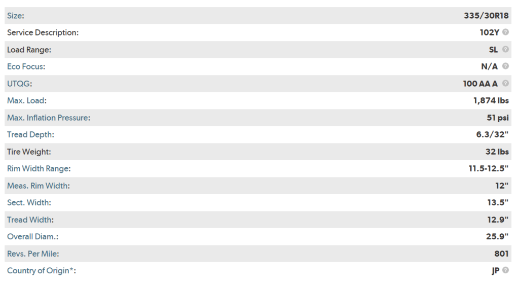
Looking at 12″-14″ wide tires that can realistically be driven on the street and fit on an 18″ wheel, I have found the Toyo R888R 335/30R18. It has a 25.9″ height, 13.5″ cross section width, 12.9″ tread width, and fits on a 12″ wide wheel.
Bridgestone, BF Goodrich, Continental, Nankang, and Hoosier make race tires in this size as well.
C6 Corvette Z06 brakes have 14″x32mm rotors with 6 piston brembo calipers that fit inside an 18″ wheel and are available for under $2000 in the second hand market. Those brakes fit on a C6 Corvette ZR1 33 spline rear hub that allows for a beefy axle shaft and mounts to the spindle/upright with a convenient 3 bolt flange. I can run this same hub on all 4 corners since its AWD.
If I factor in the 13.5″ tire width, that makes the Track Width come out to 1707.1mm (67.21″). Which is right in the ball park with several of the other GT3 cars.
Then I can use the 0.59 to 0.68 track ratio window from the example cars above to find wheelbases that work with a 67.21″ track width.
Low:
Medium:
High:
The last constraint consideration for wheelbase and track width is if I were planning to use body panels from an existing car on the exterior of this frame. While I considered the idea of using an existing car body over the top of this frame, I think (for the sake of the challenge and making it my own) that I want to design my own body work for the exterior. I plan on taking inspiration from existing cars in the form of using existing headlights, tail lights, windshields, windows, etc. However the body lines of the car will be my own. So that being said, I can pick my own wheelbase and track width within the window of numbers listed above.
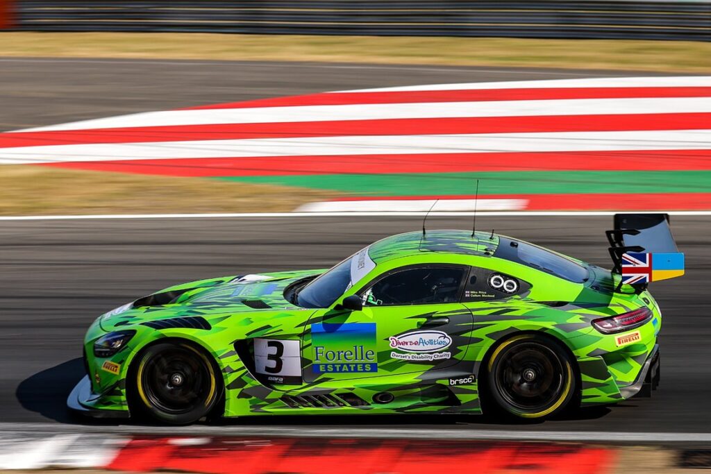
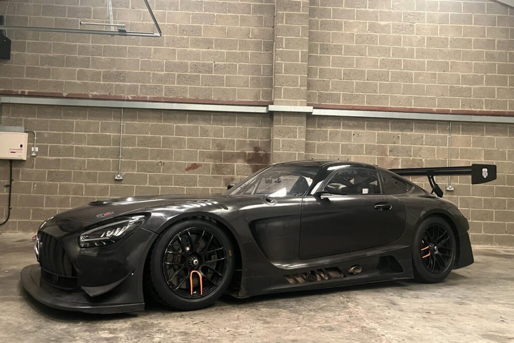
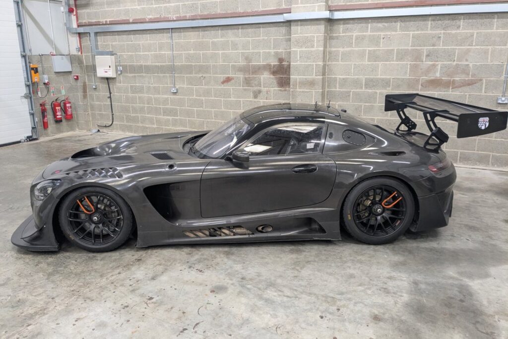
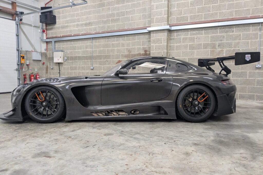
That being said, It would be nice to have a back-up plan if my body design attempts don’t look good enough. So I am going to pick the wheelbase of an existing front-mid-engine car that I like as my backup. I will use the wheelbase of the Mercedes AMG GT EVO which is 2635mm (103.7in). This makes it longer than the Porsche, but shorter than the other GT3 cars.
So now I have the following variables defined.
Overall Width: 2050mm
Track Width: 1707.1mm
Wheelbase: 2635mm
Track Ratio: 0.648
Wheel Specs: 18″ x 12″
Tire Specs: 335/30R18 (25.9″x13.5″)
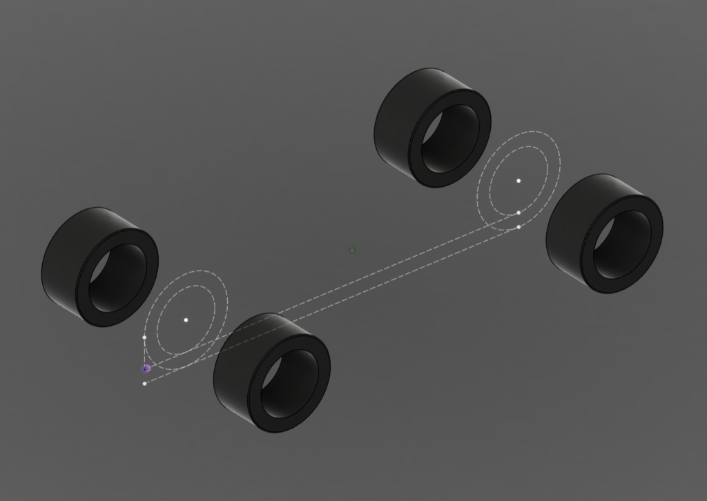
The next step will be to put 4 tires on the ground plane of an empty cad file in the right location for the chosen track width and wheelbase.
Then I will scan the main components of the drivetrain using a 3d scanner and import them into the file between the 4 tires and make sure that the drivetrain can fit within the wheelbase.
Then I will start modeling frame tubes to bolt everything together, and then move on to double wishbone suspension design.
Disclaimer: I don’t know what i’m doing. But this site is a chronicle of my figuring it out. There is probably a better way to do what I have outlined here, and I will eventually make my way there eventually.
These posts will serve as a historical archive of long format information dumps of where my mind was at the time of writing, for refreshing my memory in the future and tracking my own progress.
I often learn by doing something wrong until I figure out how to do it less wrong. Readers should not take these posts as instructional. These are a record of what I did, not what should be done, and they are not meant to be used as how-to’s.
In short, You should not do what I do unless you love the pain of failure.
A high power light weight race car similar to an IMSA GT3 car but front-mid-engine all wheel drive, that can be driven on the street and goes around turns fast with lots of grip.
At the time of writing this post, this is the plan:
Design a custom frame in Fusion and have the tubes cnc cut, bent, and notched so they arrive ready to fit together and weld.
Use OEM factory parts for major components like engine, transmission, differentials, brakes, steering rack, etc.
3D Print digitally designed body parts in pieces, bond them together, use them as a plug to build a mold off of, and then make carbon body panels to fit over the custom frame.
Specs
Power: 900-1000whp
Weight: <2500lb without driver
Drivetrain: Front-Mid-Engine AWD (FM4)
Engine: Toyota 2JZ-GTE I6
Fuel: E85
Transmission: AWD BMW ZF 8HP 8 Speed Automatic or Quaife 91G Nissan Skyline GTR Sequential
Differentials: Ford 8.8″, Nissan GTR, or Subaru R160/R180
Suspension: Custom spindle and double wishbone to optimize geometry
Brakes: Chevrolet Corvette C7 Z06 14.6″ 6 Piston Brembos
Wheels: 18″x12″ Square
Tires: 335/30R18 (25.9″x13.5″)
Frame: Custom tube
Body/Aero: Custom 3d Printed plug turned into mold for carbon fiber final layup
Design Considerations & Constraints
Guiding Concepts
Must be “streetable”
must run on fuel available at gas stations
must have a full charging system and cooling system for extended drives
must have a ride height that can make it over curbs and speed bumps.
Engine and Transmission both placed completely between the front and rear axle lines.
Use the lightest components that will achieve the end goal within my available funds at the time
Optimize center of gravity (keep things low to the ground and close to the middle of the car)
OEM Components should be reasonably priced and readily available when possible
Suspension
Optimize Camber, Caster, Scrub Radius, steering angle for the frames dimensions.
Mount everything as close to the center of the car and as low as possible
Optimize self centering, roll, squat, and dive
Steering
Make the steering as responsive as possible without instability in straights
Power Delivery
Keep the torque high and the power delivery responsive for quick acceleration recovery existing corners
Shift using paddles on the steering wheel
Slip based traction control using all 4 wheel speeds.
Braking
Make the car stop as aggressively as possible without making the car harder to drive fast into turns
Mount the brakes as close to the center of the ground and as low as possible.
Minimize unsprung weight and rotating mass
These are the initial building blocks of the plan. They may change, but many of the decisions from here will require an initial plan so this is the information those next decisions will be driven by.
Here is my tentative order of operations:
Pick a Tire
Pick an overall vehicle width
Use the tire dimensions to calculate Track Width
Use the track width to choose a wheel base within a track ratio of 0.55 to 0.65.
Digitally model the 4 tires on a ground plane at the appropriate track width and wheel base locations.
Choose an engine, transmission, and differentials that will fit within the track width and wheel base
Import scans of the engine, transmission, and differentials into the model and place them where they need to go in relation to the 4 tires.
Pick a Wheel Hub/Bearing & brake setup
Use the wheel hub/bearing dimensions to design a double wishbone spindle with a reasonable inclination angle that creates a zero scrub radius and has steering arms that point at the rear diff.
Choose a steering rack
Model the steering rack mounts so that it is in an optimal location
Use the completed hub/spindle/brake dimensions to create a wheel with the necessary dimensions to fit
Model the lower frame tubes necessary to hold the engine, transmission, and differentials in place with removable subframes.
Import a sample exterior body scan to aid in the placement of various components like the drivers seat
Import a drivers seat model and place it in the best position
Design the control arms to attach the spindles to the frame via a removable subframe that also locates the differential. Include provisions for adjustability.
Design the steering tie rods to intersect with the instant centers created by the upper and lower control arms.
Design the push rod suspension. Locate the coilovers low and central. Design the bell crank push rod linkage.
Design a sway bar setup
Model axles that connect the spindles to the differentials.
Import scans of the brake calipers and rotors
Model brackets to mount the calipers to the spindle low and centralized.
Model steering shaft and column to steering wheel.
Disclaimer: At the time of writing this post, I don’t actually know how to do any of this. So I will have to figure it all out as I go.
Disclaimer: I don’t know what i’m doing. But this site is a chronicle of my figuring it out. There is probably a better way to do what I have outlined here, and I will eventually make my way there eventually.
These posts will serve as a historical archive of long format information dumps of where my mind was at the time of writing, for refreshing my memory in the future and tracking my own progress.
I often learn by doing something wrong until I figure out how to do it less wrong. Readers should not take these posts as instructional. These are a record of what I did, not what should be done, and they are not meant to be used as how-to’s.
In short, You should not do what I do unless you love the pain of failure.